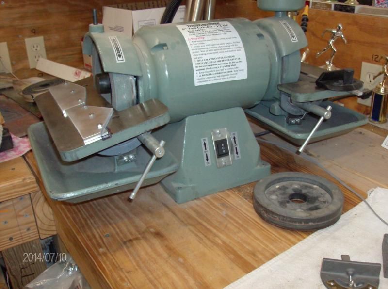
Those that read my posts have probably seen the tool grinder I use to shape/sharpen my lathe tool bits:
It's a cheep Harbor Freight copy of a Baldor. Harbor Freight = apx $150.00. Baldor = $1,200.00 plus the grinding wheels.
Now I've read horror stories of the H.F. grinder vibrating so bad that it would walk around a bench top so bolting it down was required. I've been lucky with this one as the vibration was not bad. It would sit solidly on the bench without needing to bolt it down. The wheels on the H.F. model did "wobble" out of the box, but that was easily corrected by dressing the wheels with a diamond tipped grinding wheel dresser. So after dressing the wheels they were true in relation to the table and everything worked fine. But, I wanted to run a 220 gr diamond hone wheel. You can't "dress" that wheel. Now with apx 15 thousandths run-out I was unable to use the diamond wheel. With that much run-out anything that you tried to put up against the wheel would actually be "kicked" back at youPlease note: The Baldor brand guaranty's .002 run-out or less.
So a bit of work would need to be done to get this machine running true. Here I have to give some credit to a couple of people. There are two people that have done a series of videos on Youtube on how to get these cheep HF copies running the way they should. The first one is a 5 part series by ghostses. Part one of his series is here: https://www.youtube.com/watch?v=lSi3lucyRQo His big thing is to put the assembled shaft on a lathe and true everything up. The next video series is by Keith Fenner. His big thing is to replace a few parts that are so badly out of round they are causing the mounting plates to wobble. Part one of his series is here: https://www.youtube.com/watch?v=9xRy8wGfcIk
I took information from both of these sources and got to work. . .
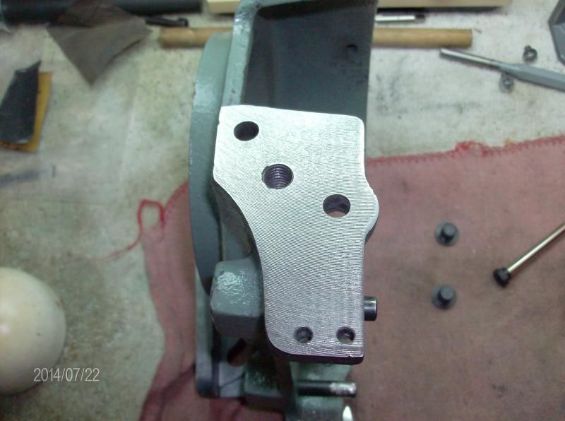
Before we get into the nuts and bolts of the run-out issue there are a few other things to discuss. First is the general lack of de-buring done on the table and supports.
Going around the outside edge of the table I used a 1 inch belt sander with a fine grit belt. The other issue was the hole that the mounting stud goes through. I tapped out the mounting studs and hand sanded the hole to take off the burs.
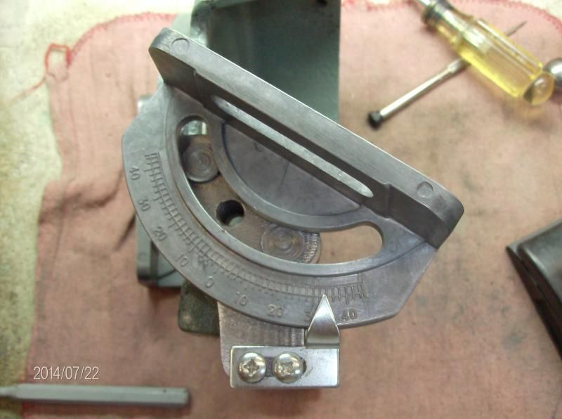
Now on to the mounting brackets for the table. THEY ARE NOT SQUARE. You can square them up with a mill, or (as I did) just using a disc grinder. After they are squared up you'll need to de-bure them also.
Oh, back to the table before I forget. The mounting point on the bottom of the table is machined, but for some reason it is painted over. Be sure to get that paint off for a nice solid contact point.
Ok, what next? The table mounts to the table brackets, and the brackets then mount to the grinder. That mounting point is also covered in paint that needs to come off. I found it helpful to tap out the studs here also. This is also where the pivot point is that allows the table to be set at different angles. I dab of grease or oil here is very helpful when assembling.
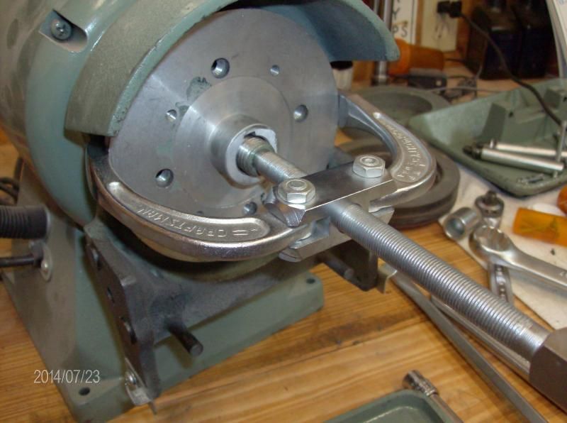
Alright, now lets get into the teardown of the guts of the grinder. After pulling the guard off, you'll need to remove the mounting/backing plate. (this is the plate that the grinding wheel mounts to) Both video series show to use a couple of long screwdrivers to pry the plate off. After doing that on one side I looked for a better way. A gear puller! Yeah, that's the ticket. Honestly, I almost didn't need to use a wrench on the gear puller. It worked great!
Ok, here is where the two video series depart. One doesn't disassemble any further but removes the shaft and goes to the lathe to true things up. The other continues to disassemble the shaft components and finds things that need to be replaced. As I said at the top, I took the best of both series.
To continue the disassemble you need to remove a roll pin from a blind hole. Keith does this by cross drilling a hole all the way through and tack welding a rod to the roll pin to drive it out. I came up with what I thought was a better idea. The plan was to tap the roll pin with an 8x32 tap, screw in a machine screw, and pull it out with a claw hammer. It didn't work out that way. It worked out better:
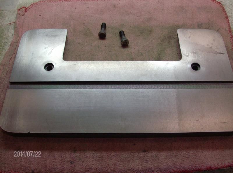
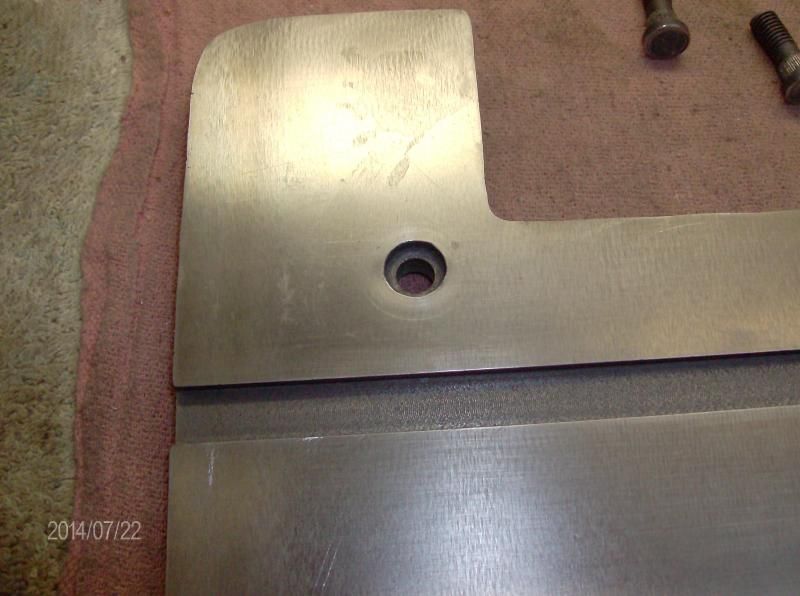
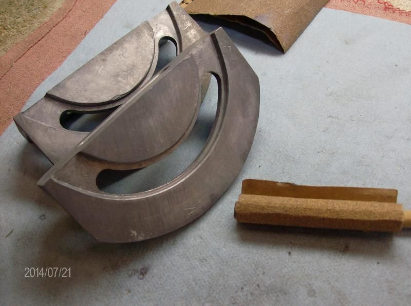
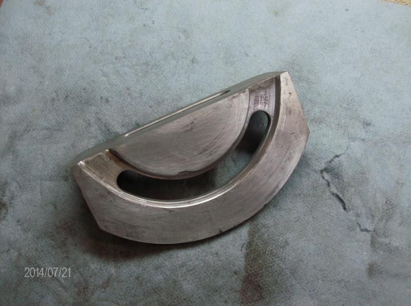
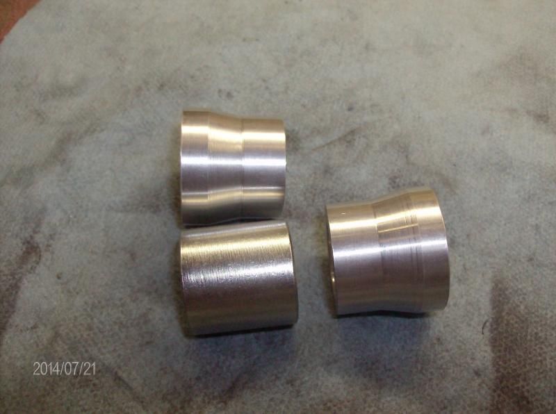
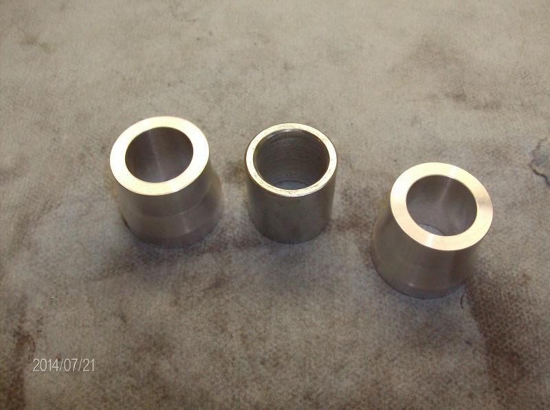
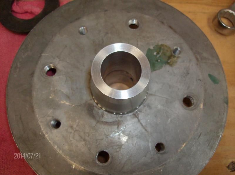
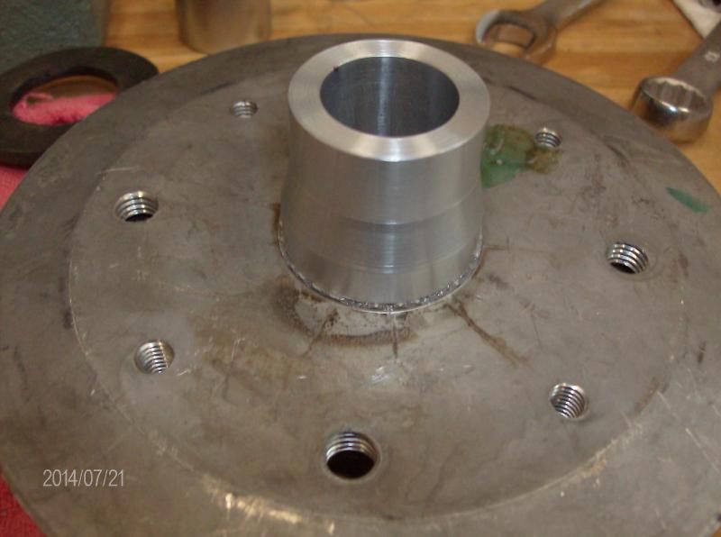
Behind the roll pin is a spacer that butts up to the bearing. This spacer is JUNK - and that's being kind to junk. Not only are the shoulders not square, the I.D. is WAY too large and it is out of round. Yes, the hole through the spacer is not centered in the middle of the spacer. A new spacer is in order here. I used some round stock I had on hand. It matches the matting surface of the mounting/backing plate and tapers down to meet the bearing. Here's some photos with the old spacer.
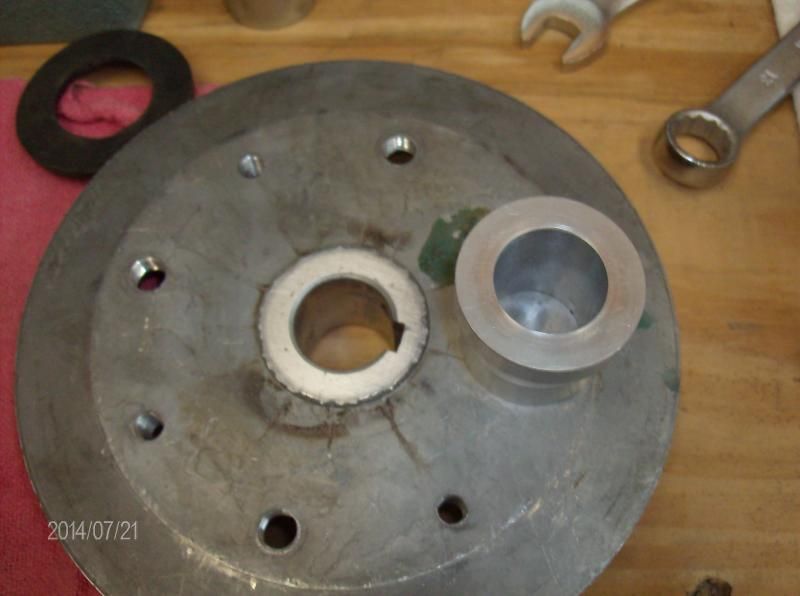
photos of the new spacer with the backing plate:
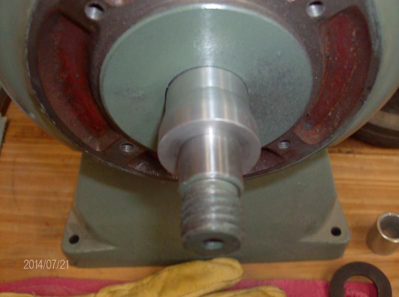
Here's a photo of the spacer on the shaft. It's not all the way down though because it's a bit stuck on some paint on the shaft. I'll take care of that paint in a bit.
This made an improvement, but things still were not right.
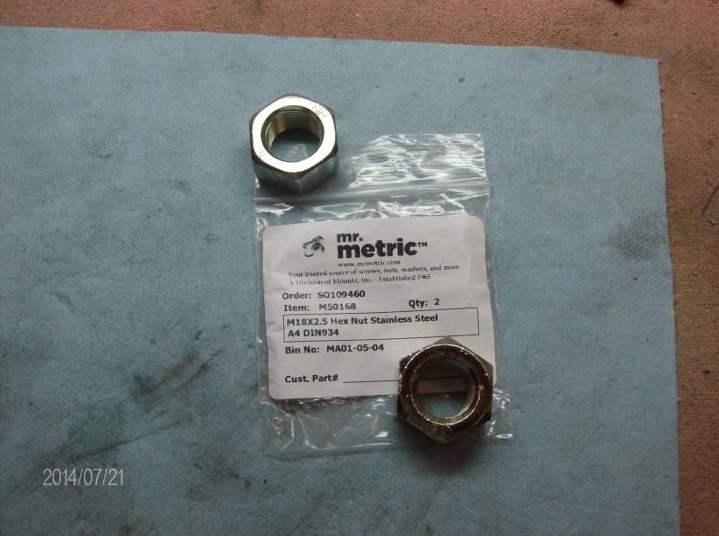
At this point in Keith's series, Keith had determined that the M18X2.5 nuts were not true. The nuts on mine were horribly wobbly. Keith made a couple of nuts out of Brass, but I ordered a couple of Stainless nuts from "Mr. Metric".
And here I ran into a bit of a stopper. Mr. Metric did not send me the right nuts. One was some kind of plated thing (with the plating pealing off) and the other was the wrong pitch of 1.5 not the 2.5 I ordered. Made a call and explained. Said they'd investigate and call me back. I was a bit nervous at this but . . . They called back an hour later with an apology. The bin that was supposed to be stainless m18x2.5 was filled with an assortment of M18 nuts. The guy said he had two stainless M18.2.5 in hand and would have them out to me in the morning. Can't ask for better really.
Ok, at this point Keith was done. IIRC he had his down to .002 run-out. I continued to remove the shaft and put everything onto the lathe to true things up. I'll show that in my next post. I'll just tack it on on this thread later today. Please stay tuned. . .

- Forum
- AK-47.NET ™ Forums
- AK-47.NET ™ Discussion Forum
- Gunsmithing Corner
- Tool Grinder Improvement Program




 Reply With Quote
Bookmarks